"Hello World" with your Shoto SteamVR Tracking HDK
Unbox the HDK
Plug the Shoto Core Module with a USB cable. Micro-USB connection on the Shoto Core Module.
Check for blinking light
Launch Lighthouse Console
Make sure you have the latest version of Lighthouse Console
What command do you run in Lighthouse Console to get the HDK to do something?
Remove power from the Shoto Core Module by disconnecting the micro-USB connector
Plug in both flex cables into the Shoto Core Module
Include photo and video of plugging in the flexes
Plug the micro-USB connector back into the
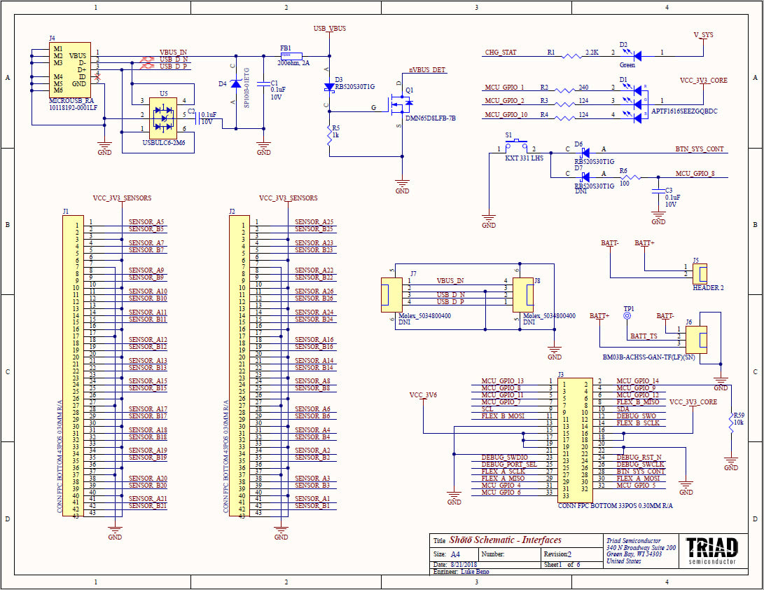
Sheet 1 - Connectors & Indicators
Flex Connectors
Sheet 1 of the Shoto Core Module contains the high-density flex connectors J1, J2, and J3. J1 and J2 are 43-position FPC connectors with 0.3mm pin spacing. These two connectors are used to attach the Sensor Flex Assemblies to the Shoto Core Module. The J3 connector is a 33-position FPC connector with 0.3mm pin spacing that connects the Shoto Core Module to an optional Application Board.
This Application Board is not part of the Shoto HDK because the application board will be unique to your particular application. For initial concepts on this board please see: help.triadsemi.com/steamvr-tracking/how-to-add-a-button-to-the-shoto-hdk
Battery Connections
A battery can be hardwired to the Shoto Core Module by soldering the battery's plus terminal to J5-1 and the battery's minus terminal to J5-2.
A battery with a standard JST-style connector can be attached via connector J6.
For more information on batteries and battery connections to the Shoto Core Module see: help.triadsemi.com/steamvr-tracking/shoto-steamvr-hdk/what-batteries-work-with-the-shoto-hdk
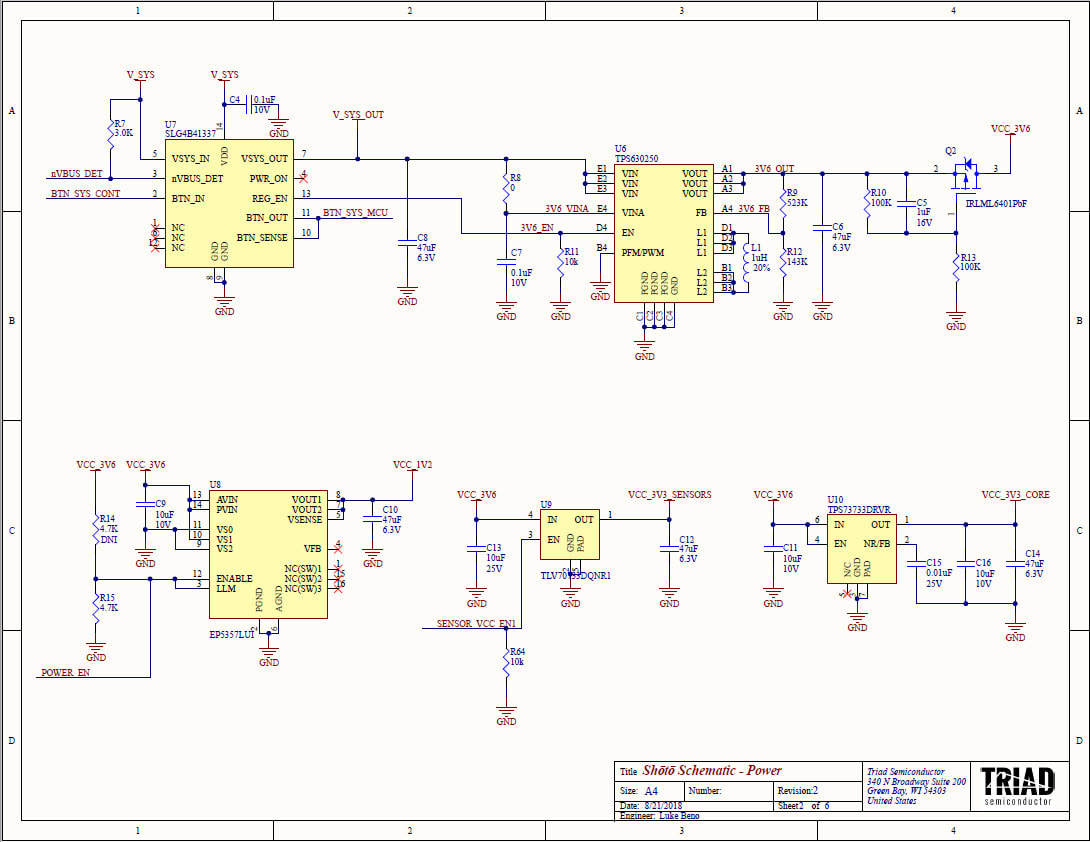
Sheet 2 - Power Management
The power management ICs on sheet 2 generate the various power rails needed by the Shoto HDK. See Sheet 3 for more info on the power architecture.
Silego Part, U7 SLG4B41337
The component U7 is a custom programmed Silego part with custom part number SLG4B41337. This custom part is has a minimum order quantity of a 3,000 pieces reel. If you have plans to make larger volumes of custom tracked objects please contact Triad about options to reduce total BOM cost.
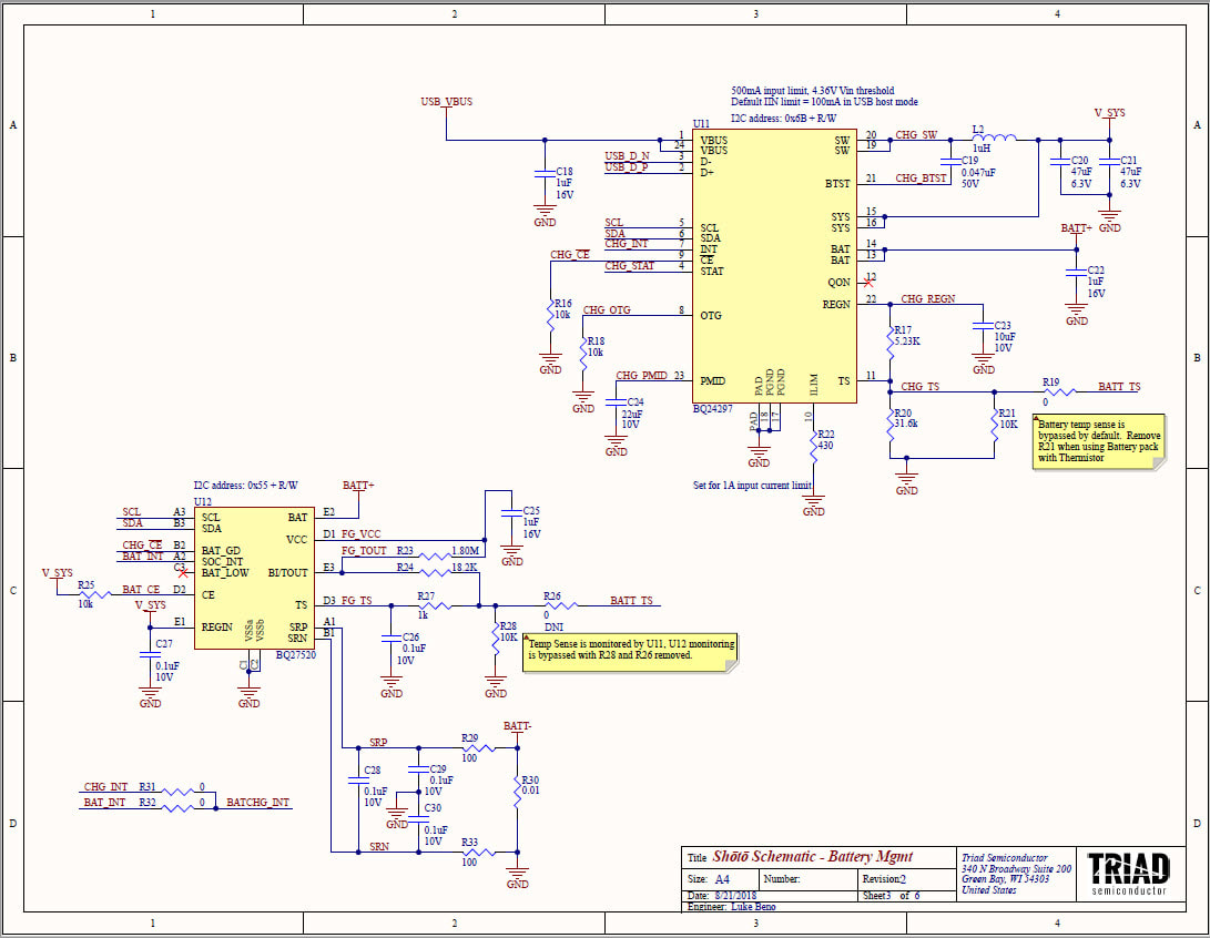
Sheet 3 - Main Power Management and Battery Management
The BQ24297, U11, and U12 (BQ27520) manage USB input power conversion to V_SYS and manage the charging, monitoring and power conversion from the connected battery.
The battery temperature sensor is bypassed by default in the HDK. If using a battery pack with a thermistor then remove R21.
The battery temperature sensor is bypassed by default in the HDK. If using a battery pack with a thermistor then remove R21.
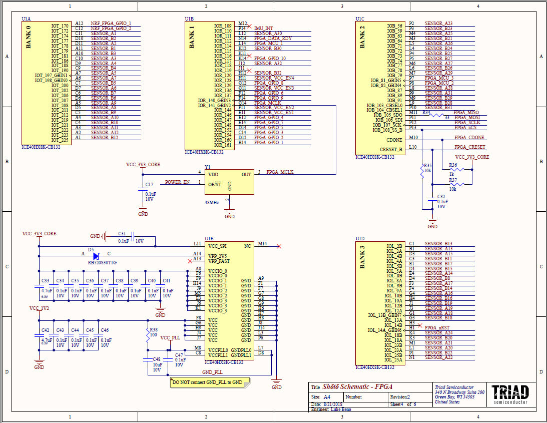
Sheet 4 - Lattice FPGA
The Lattice FPGA (ICE40) connects up to 32 Light-to-Digital sensors to the Shoto Core Module. The FPGA supports two digital connects per sensor for Data and Envelope signaling. The bitstream, or configuration, for the U1 FPGA is Valve Software Corporation proprietary. The bitstream is downloaded from the Cortex-M4 micro on the Shoto Core Module for SteamVR Tracking Operation.
Note: If you are interested in using the Shoto HDK a general-purpose "data capture" board then please see Shoto bare-metal Hacking.
Note: If you are interested in using the Shoto HDK a general-purpose "data capture" board then please see Shoto bare-metal Hacking.
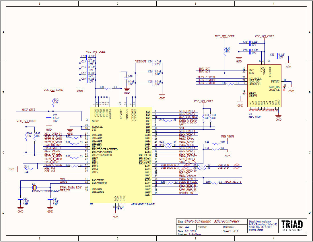
Sheet 5 - Microprocessor and IMU
Cortex-M4 Processor
The Shoto Core Module uses an Atmel ATSAMG55 Cortex-M4, reference U2, as the main micro for the HDK. The SteamVR Tracking software contained in the U2 micro is proprietary to Valve Software corporation. The SteamVR Tracking HDK/SDK provides the U2 software as a downloadable binary file. Un-programmed Shoto Core Modules can be programmed via a JTAG interface. Once the U2 micro has been programmed it can be updated by a USB bootloader as Valve makes 'watchman' software updates.
Once configured, the U2 micro is responsible for downloading the Lattice FPGAs configuration information.
Note: If you are interested in using the Shoto HDK a general-purpose "data capture" board then please see Shoto bare-metal Hacking.
IMU
Component U3 is a Invensense MPU-6500. See MPU-6500 Datasheet
The MPU-6500 is a 6-axis Inertial Measurement Unit (IMU). The MPU-6500 combines a 3-axis gyroscope, 3-axis accelerometer, and a Digital Motion Processor™ (DMP) in a 3x3x0.9mm package.
If you are working on a tracked object that is exposed to high G-shocks then you might be interested in Project SPANK.
The Shoto Core Module uses an Atmel ATSAMG55 Cortex-M4, reference U2, as the main micro for the HDK. The SteamVR Tracking software contained in the U2 micro is proprietary to Valve Software corporation. The SteamVR Tracking HDK/SDK provides the U2 software as a downloadable binary file. Un-programmed Shoto Core Modules can be programmed via a JTAG interface. Once the U2 micro has been programmed it can be updated by a USB bootloader as Valve makes 'watchman' software updates.
Once configured, the U2 micro is responsible for downloading the Lattice FPGAs configuration information.
Note: If you are interested in using the Shoto HDK a general-purpose "data capture" board then please see Shoto bare-metal Hacking.
IMU
Component U3 is a Invensense MPU-6500. See MPU-6500 Datasheet
The MPU-6500 is a 6-axis Inertial Measurement Unit (IMU). The MPU-6500 combines a 3-axis gyroscope, 3-axis accelerometer, and a Digital Motion Processor™ (DMP) in a 3x3x0.9mm package.
- Onboard 512-byte FIFO
- I2C Bus
- The gyroscope has a programmable full-scale range of ±250, ±500, ±1000, and ±2000 degrees/sec.
- he accelerometer has a user-programmable accelerometer full-scale range of ±2g, ±4g, ±8g, and ±16g.
If you are working on a tracked object that is exposed to high G-shocks then you might be interested in Project SPANK.
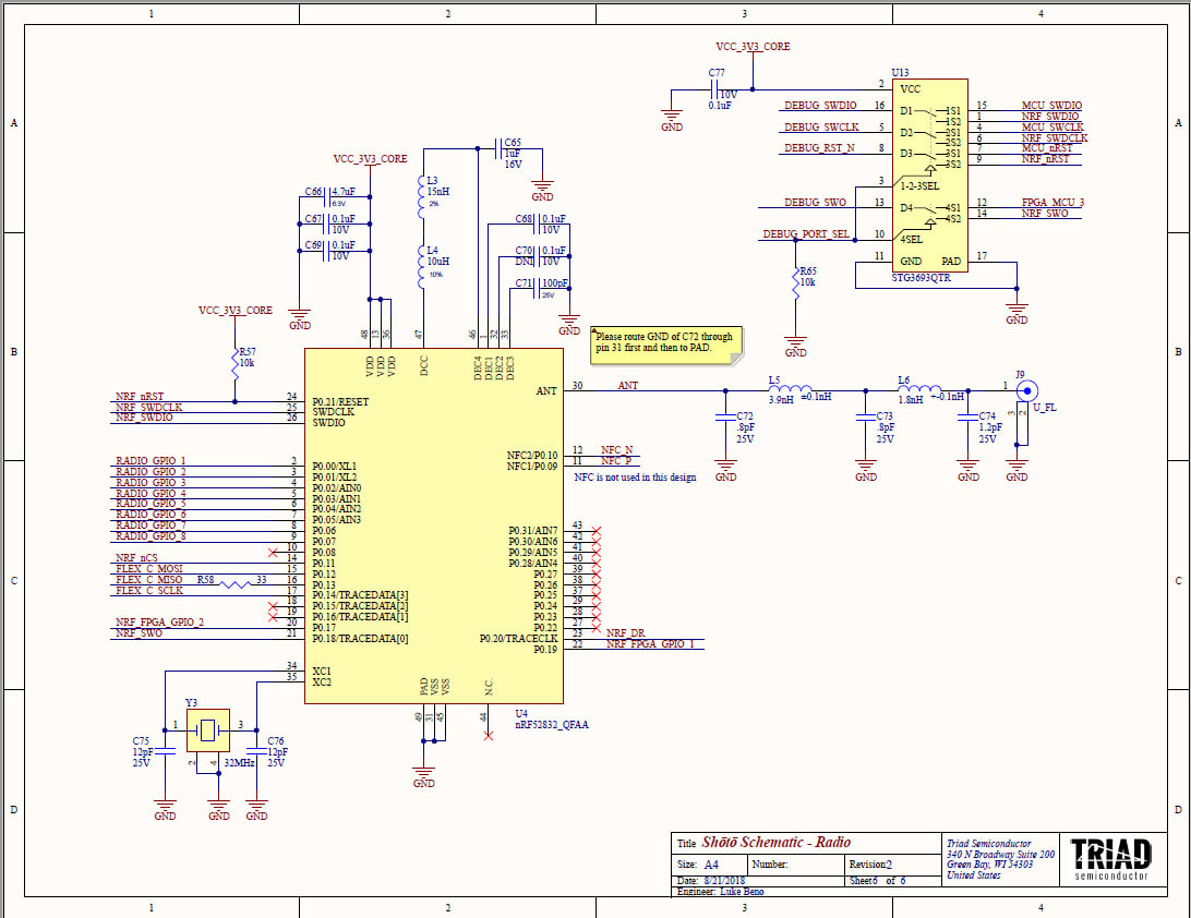
Sheet 6 - nRF Radio and Switch
The nRF52832, U4, is a Nordic 2.4GHz radio. An external antenna can be connected to the Shoto Core Module via J9.
The Nordic Radio operates at 2.4GHz and utilizes a non-standard communications protocol other than Bluetooth. The software that is configured onto the radio is Valve Software Corporation proprietary.
Note: If you are interested in using the Shoto HDK a general-purpose "data capture" board then please see Shoto bare-metal Hacking.